Vice Virga Manual#
8-input, 8-output sequential/addressable switch with manual, trigger, and CV control, plus three grouping options, multiple switching directions, and randomization
Screen reader accessible documentation
Overview#
Vice Virga is an 8-input, 8-output sequential/addressable switch with a plethora of features and extensive patchability. Vice Virga can be configured as a single 8-channel switch, two 4-channel switches, or four 2-channel switches. Equal parts automated patch arranger and performance tool, Vice Virga has loads of switching control options. Whether you want to chain sequencers, swap outputs on an oscillator, remix a trigger pattern, or mix up every connection in a patch just to see what happens, Vice Virga can do it!
- Type: Sequential switch
- Size: 8 HP
- Depth: 0.8 inches
- Power: 2x5 Eurorack
- +12 V:
40 mA - -12 V:
20 mA
Etymology#
Vice -- from Latin: "Alternately"
Virga -- from Latin: "Switch
"Alternating Switch"
Power#
To power your Noise Engineering module, turn off your case. Plug one end of your ribbon cable into your power board so that the red stripe on the ribbon cable is aligned to the side that says -12 V and each pin on the power header is plugged into the connector on the ribbon. Make sure no pins are overhanging the connector! If they are, unplug it and realign.
Line up the red stripe on the ribbon cable so that it matches the white stripe and/or -12 V indication on the board and plug in the connector.
Screw your module into your case before powering on the module. You risk bumping the module's PCB against something metallic and damaging it if it's not properly secured when powered on.
You should be good to go if you followed these instructions. Now go make some noise!
Noise Engineering modules are reverse protected. If you accidentally installed it with the red stripe up, simply remove the power and place it correctly.
A final note. Some modules have other headers -- they may have a different number of pins or may say "not power". In general, unless a manual tells you otherwise, do not connect those to power.
Input and output voltages#
Vice Virga's CV input has a 0 V to 5 V range; voltages outside this range will be clamped to 0 V or 5 V.
Trigger inputs trigger around 3.5 V.
The main inputs and outputs can be used with any type of signal from -10 V to 10 V.
Interface#
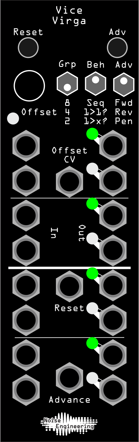
- Reset
- Resets Vice Virga to step 1, or the value set by the Offset CV/encoder.
- Adv (button)
- Advances a step each time it's pressed, following the Adv and Beh settings.
- Offset
- Manual offset control. Each encoder click moves up or down one step, no matter the mode. Tapping the encoder resets the offset. Offset changes where Vice Virga resets to when Reset is pressed/triggered.
- Grp (Group)
- Changes the switch grouping.
8: A single 8-input, 8-output switch.4: Two 4-input, 4-output switches.2: Four 2-input, 2-output switches.
- Beh (Behavior)
- Changes switch-routing behavior.
Seq: Vice Virga advances outputs sequentially following the selected Adv direction each time Advance is pressed/triggered. When Vice Virga is reset, the input/output routing is initialized: In 1 goes to Out 1, In 2 goes to Out 2, etc., respecting any offset.1>1?: Vice Virga advances outputs randomly, respecting the Grp setting, and only allowing inputs to be routed to a single output. The Offset encoder/CV offsets the randomized routing. When Vice Virga is reset, the input/output routing is initialized: In 1 goes to Out 1, In 2 goes to Out 2, etc., respecting any offset.1>x?: Vice Virga advances outputs randomly, respecting the Grp setting but allowing inputs to route to any number of outputs (including 0). The Offset encoder/CV offsets the randomized routing. When Vice Virga is reset, the input/output routing is initialized: In 1 goes to Out 1, In 2 goes to Out 2, etc., respecting any offset.
- Adv (switch)
- Changes the direction Vice Virga advances in
Seqmode when triggers are received at the Advance jack, or the Adv button is pressed.
Fwd(Forward): Vice Virga advances from top to bottom.Rev(Reverse): Vice Virga advances from bottom to top.Pen(Pendulum): Vice Virga advances from top to bottom to top again.
- Inputs 1-8
- Switch inputs. Suitable for CV, gates/triggers, and audio.
- Outputs 1-8
- Switch outputs. Suitable for CV, gates/triggers, and audio.
- Offset CV
- CV input for offset. Offset changes where Vice Virga resets to when Reset is pressed/triggered.
- Reset
- Trigger input for Reset. Resets Vice Virga to step 1, or the value set by the Offset CV/encoder.
- Advance
- Advances the switch, following the Adv and Beh settings.
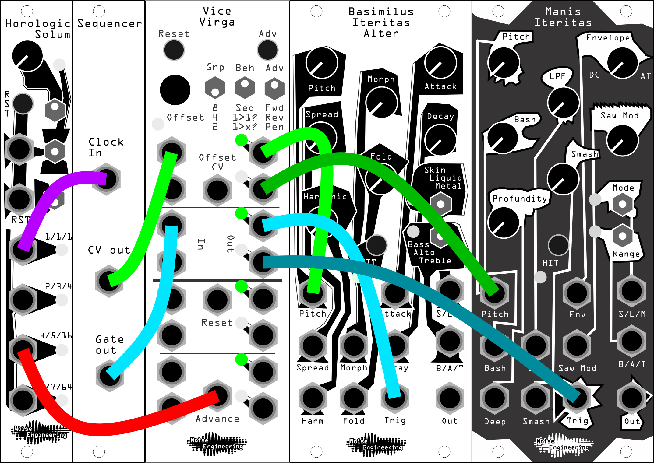
Patch Tutorial#
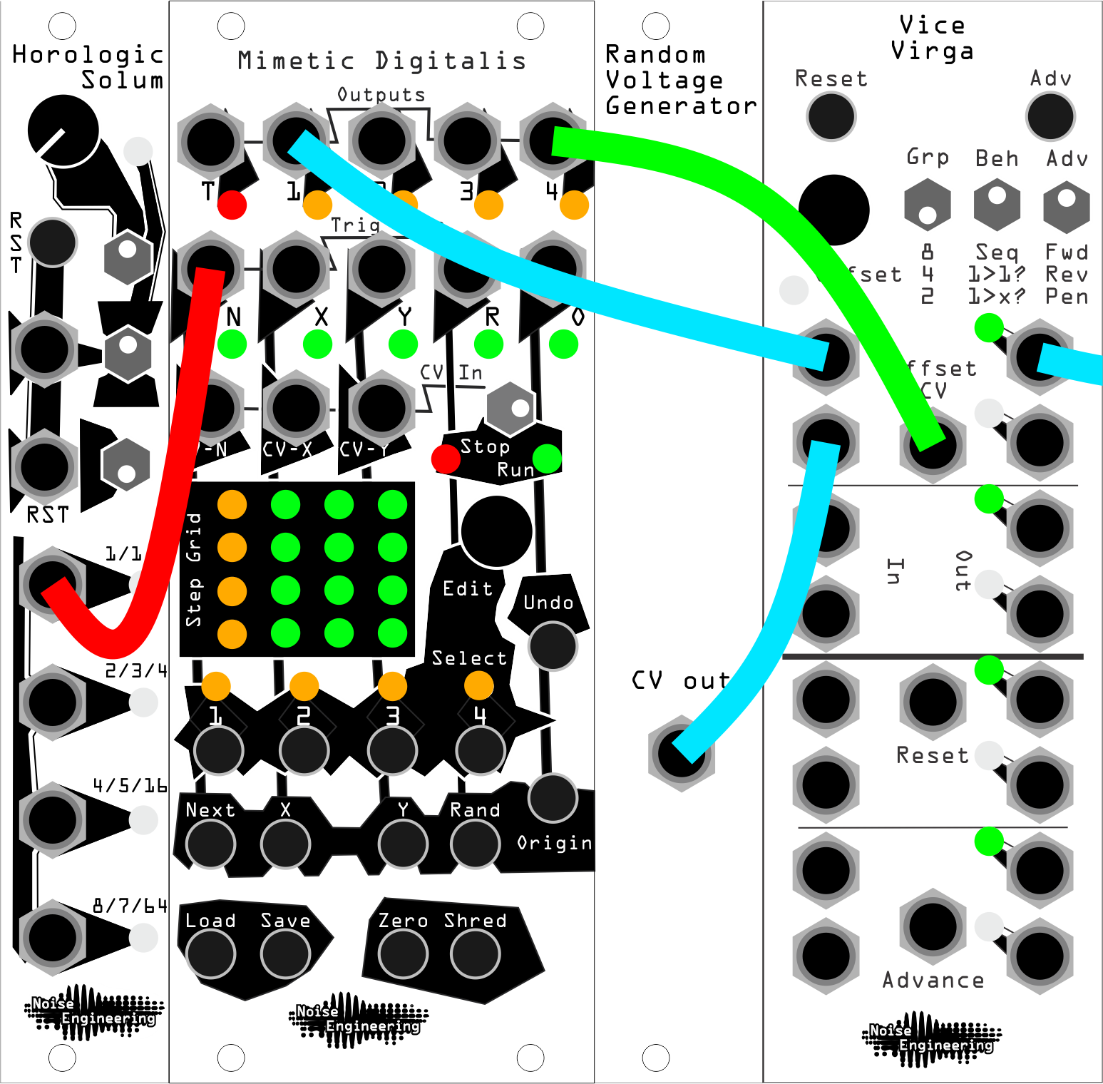
- Chaining Sequencers
- Chain sequences together with ease.
1. Patch multiple sequencers, or a sequencer with multiple outputs, to Vice Virga’s
Injacks. If chaining two sequencers/channels, setGrpto2. If chaining four, setGrpto4. 2. Patch VV’sOut 1to your destination. 3. Mult a clock to your sequencers and to a clock divider (or use a clock generator with divided outs) 4. Patch an appropriate division to theAdvancejack on VV: for instance, in the illustrated patch, Mimetic Digitalis (our sequencer) has 16 steps, so we’ll use a /16 output to advance VV.
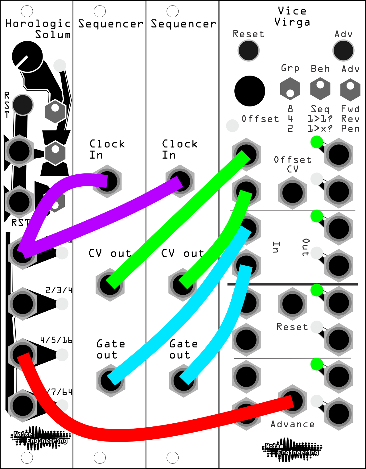
- Chaining Sequencers (continued)
- If you’re using two sequencers, both gates and CV can be extended with a single VV:
1. Set VV to
Grp 2. 2. Patch the CV and gate outputs of the first sequencer to VVIn 1andIn 3respectively, 3. Patch the CV and gate outs of the second sequencer to VV inputsIn 2andIn 4. 4. Clock the sequencers and VV as in the first example.
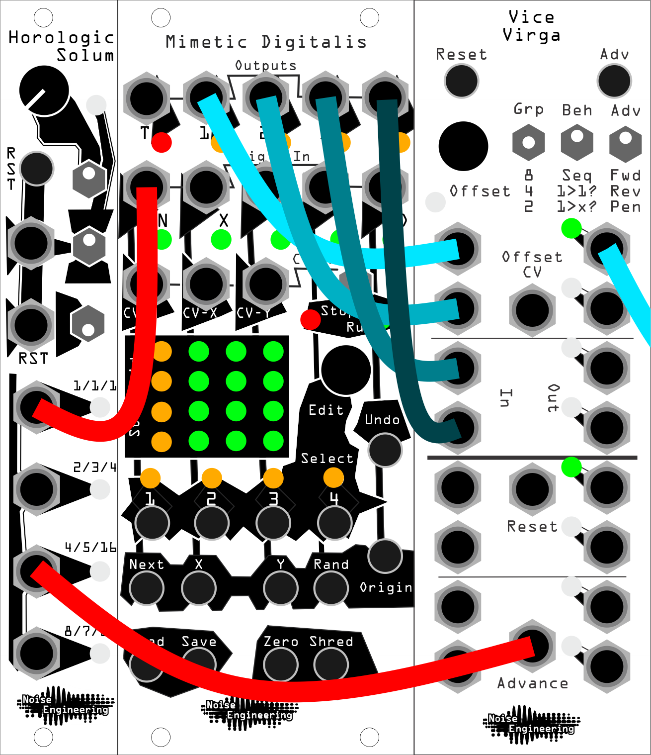
- Sequencer Remixer
- VV can also combine sequencers with other voltage sources to create new variations.
1. Set VV’s
Grpsetting to2. 2. Patch a CV sequencer toIn 1, and a random source toIn 2. 3. Patch a slow clock toAdvance. 4. VV will pass the preprogrammed CV sequence through when in position 1, and the random source while in position 2.
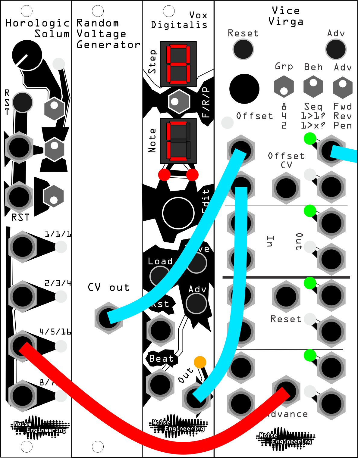
- Sequencer Remixer (continued)
- Switching can also be done with CV for more control. This allows for some creative sequencing when using something like Mimetic Digitalis which has multiple CV outs.
1. Create the same patch as above: Set
Grpto2, output1of Mimetic Digitalis goes toIn 1on VV, and a random source goes toIn 2. 2. Instead of patching a clock toAdvance, patch output2from Mimetic Digitalis to theOffset CVjack on VV. 3. Program the CV on channel2of MD: each step with low CV will allow the preprogrammed sequence through, and each step with high CV will pass through the random CV.
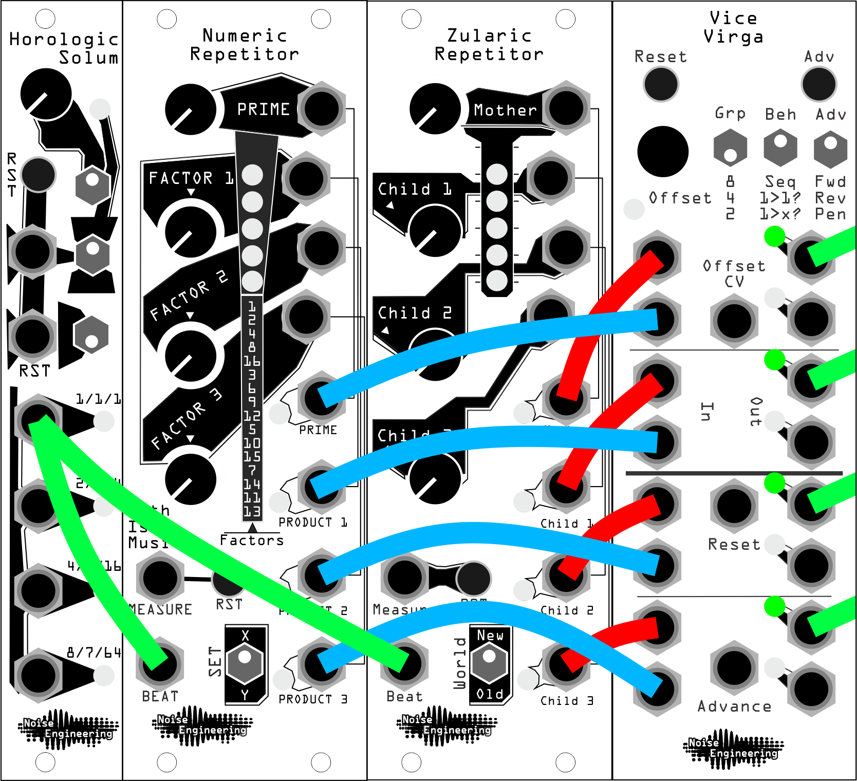
- Trigger Remixer
- Switching between groups of trigger sequences is a useful technique when patching with percussion. Here, we’ll swap between a Numeric Repetitor and a Zularic Repetitor, but this exact patch will work with any set of trigger sequencers.
1. Patch the four outputs of NR to VV
In 1,In 3,In 5, andIn 7. 2. Patch the ZR outputs to VV inputsIn 2,In 4,In 6, andIn 8. 3. Patch VV outputsIn 1,In 3,In 5, andIn 7to some triggered voices. 4. SetGrpto2, and use theAdvbutton orOffsetencoder to swap between patterns. For extra variation, add some randomization: the middle and bottomBehsettings create randomized routings each timeAdvis pressed.
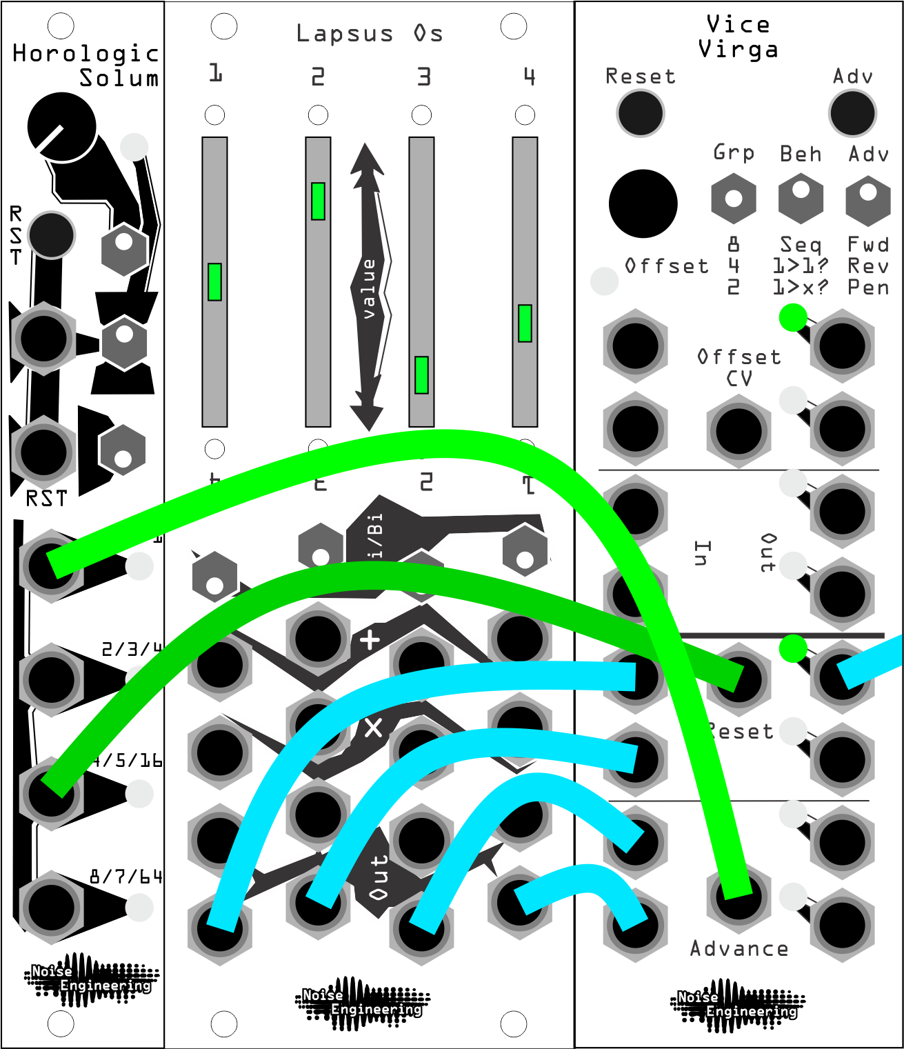
- Step Sequencer
- Patch up your own sequencer with some offsets and VV.
1. Patch the outputs of Lapsus Os to the first four inputs on VV.
2. Set
Grpto4. 3. Patch clock and reset signals to theAdvanceandResetjacks on VV. 4. PatchOut 1to a CV destination. 5. Change the levels of the LO sliders to change the steps of the sequence. Try patching things like LFOs and envelopes in place of offsets to vary your sequence. To add variation to your sequence on the fly, try offsetting the switch with theOffsetencoder. This will change which step in the switch is first, giving your sequence a slight variation.
- Call and Response
- This patch alternates two voices, creating a musical conversation between two voices.
1. Patch the CV output of your sequencer to
In 1, and the gate output of your sequencer toIn 3. 2. PatchOut 1andOut 3to the respective CV and gate inputs of one voice, andOut 2andOut 4to the CV and gate inputs of another. 3. TriggerAdvancewith a clock divider, a trigger sequence, or manually to create call-and-response with a single sequence between two voices.
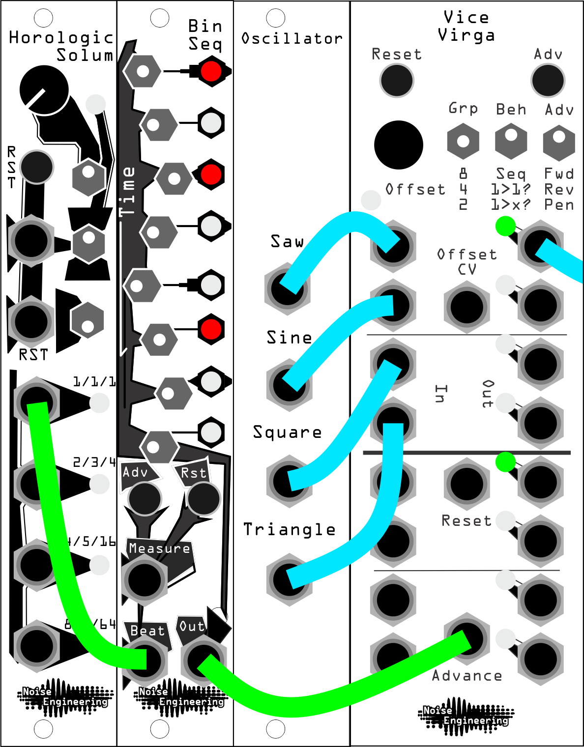
Rhythmic Audio
Create stepped audio effects that follow a trigger pattern.
1. Patch a module with multiple outputs (like an oscillator with multiple waveforms, or a filter with multiple filter outs) to the top inputs on Vice Virga.
2. Patch Out 1 to your mixer.
3. Set Grp to the appropriate setting for the number of inputs you have (for instance, if you have 2 outputs on your filter, set Grp to 2; if you have 4 outputs on your oscillator, set Grp to 4, etc).
4. Patch a trigger pattern to Adv, and VV will rhythmically swap between your sounds.
Design notes#
Vice Virga has existed, in some form or another, longer than Noise Engineering.
The first prototype was designed around the time of the conception of Ataraxic Translatron, at the suggestion of Noise Engineering friend Skyler King, aka Kittyspit. Sequential switches have been a modular synthesis staple for over 50 years, and we thought it would be fun to put our own spin on one.
Once the basic Vice Virga featureset had been ironed out, we built a prototype. The first one was built back in the days when this was just a hobby that Stephen had when he locked himself away in a spare room in the house (okay he still does that part but now he does it for more hours per day and there are a bunch of us yammering at each other on Slack the whole time). That first one languished for literally years until we dusted it off and said hey, let's do something with this! This was in the days before we had Markus, our Chief of Destruction, so we sent it off to our pal Jon for test. He found a massive design issue though...and it once again languished while other things just seemed to always take priority.
Eventually we pulled it out again, dusted it back off, and said hey, this should be an easy fix! Some hot air later and we had a redesign. And it was, again, awesome, but another small but important issue was found in testing. This one was more nefarious and a real pain. Parts were added. Parts were removed. Measurements were taken. Many measurements were taken. So many measurements. A few tears may have been shed. And then!
Finally! We had a final prototype in early 2020. We were so excited we told people about it a little later that year. Unfortunately, 2020 had other plans for us: we announced Vice Virga with great fanfare, but were unable to actually manufacture it until September of 2021.
Vice Virga is a simple module under the hood but is complex in what it can do. It was a challenge, a process, and an enigma for us in many ways, but we're very proud of how it turned out. It seems like every time we patch it up, we find a new and interesting use for it. It's got quite a story; we think it's pretty cool, and we hope you'll enjoy yours, too.
Warranty#
We will repair or replace (at our discretion) any product that we manufactured for one year after initial purchase as long as we are able to get the parts to do so. This warranty does not apply to normal wear and tear, including art/panel wear, or any products that have been modified, abused, or misused. Our warranty is limited to manufacturing defects.
Warranty repairs/replacements are free. Repairs due to normal wear, user modification, or other damage are charged at an affordable rate. Customers are responsible for the cost of shipping to Noise Engineering technicians for repair.
All returns must be coordinated through Noise Engineering; returns without a Return Authorization will be refused and returned to sender.
For immediate issues with new modules, please contact your dealer for a replacement. Otherwise, please contact us if you think one of your modules needs a repair.
Special thanks#
- Skyler King, aka Kittyspit
- Jon Barbieri
- Everyone who kept asking and hoping for it all this time.