Mimetic Digitwolis#
Next-generation four-channel CV-sequencing powerhouse with configurable routing, quantization, MIDI, and more.
Overview#
Mimetic Digitwolis is the long awaited sequel to the classic Mimetic Digitalis, our classic Cartesian performance sequencer. This heavily upgraded second edition features many customer-requested features, including customizable quantizers for both internal and external signals, internal sequence-length and clock divisions, triggerable step randomization, and a whole lot more. With fully configurable inputs, new lane output types, and a completely rethought interface, Mimetic Digitwolis retains the performable concepts of the original while unlocking entirely new ways to play a Eurorack sequencer.
- Type: Four-output CV sequencer
- Size: 10 HP
- Depth: 1 inch
- Power: 2x5 Eurorack
- +12 V:
80 mA - -12 V:
20 mA
Etymology#
Mimetic -- from Latin: "pertaining to mimes"
Digitwolis -- from Latin digitalis contracted with English two: "belonging to two fingers"
"Second finger mime of death"
Power#
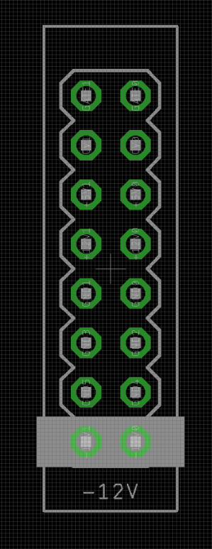
To power your Noise Engineering module, turn off your case. Plug one end of your ribbon cable into your power board so that the red stripe on the ribbon cable is aligned to the side that says -12 V and each pin on the power header is plugged into the connector on the ribbon. Make sure no pins are overhanging the connector! If they are, unplug it and realign.
Line up the red stripe on the ribbon cable so that it matches the white stripe and/or -12 V indication on the board and plug in the connector.
Screw your module into your case before powering on the module. You risk bumping the module's PCB against something metallic and damaging it if it's not properly secured when powered on.
You should be good to go if you followed these instructions. Now go make some noise!
Noise Engineering modules are reverse protected. If you accidentally installed it with the red stripe up, simply remove the power and place it correctly.
A final note. Some modules have other headers -- they may have a different number of pins or may say "not power". In general, unless a manual tells you otherwise, do not connect those to power.
About#
Mimetic Digitwolis is a highly configurable sequencer and quantizer. It features four mappable CV inputs and five mappable trigger inputs, four output lanes, and MIDI in and out on TRS type A jacks.
Each of its four lanes can be configured to output modulation CV, pitch CV, triggers, or gates, or to act as a quantizer on external CV. Each sequence can be any length from one to 16 steps, and can be navigated sequentially forwards and backwards, or with X/Y navigation in a variety of arrangements like 4x4 and 5x3. Internal clock dividers can also be applied to lanes, and sequences can be navigated with any trigger source, addressed with external CV, and/or synchronized to external clock sources like MIDI.
A number of destructive edits are also available for mapping to external triggers. Shred, the famous randomization parameter from the original Mimetic Digitalis, can now be triggered externally as well as manually. Steps can also be triggered to their minimum value. Shift offsets the entire sequence a configurable number of steps forward. Finally, stepped CV recording is possible using a trigger and external CV source.
CV and Pitch lanes can have their output minimum and maximum configured to best accommodate their destinations, and slew limiting can be applied to their outputs for smooth transitions between values. External CV can also be mapped to offset the level of a lane, and CV lanes can have their output attenuated by external CV as well.
Mimetic Digitwolis features an extensive variety of editing shortcuts, useful for randomizing entire sequences, creating ramp patterns, offsetting entire sequences, copying one lane to another, and quickly adjusting sequence length and step position.
Pitch and external quantizer lanes have configurable scales, editable either manually from the screen or with an external MIDI keyboard. When a new scale is applied to a pitch lane, the existing sequence will reflect the new scale immediately, a particularly fun behavior when using a MIDI keyboard as a performance element. Randomizations in pitch lanes using manual or triggered Shred will also respect note minimum, maximum, and scale settings, making it easy to randomly create musical sequences on the fly or in generative patches.
The internal memory can save and load into 24 slots. Saves include all sequence data and trigger and CV mappings, making it easy to jump between entirely different patches and configurations.
MIDI is also implemented globally as a clock synchronization option, and Program Change messages can be used to load saved configurations from an external controller. CV lanes will output stepped CC modulation, and pitch, note, trig, and gate lanes will output simple MIDI note sequences. Quantizer lanes will output notes based on quantized pitch and gate length, acting as a simple CV to MIDI interface. Scales can be configured with MIDI input for quantizer and pitch lanes, and the steps of CV lanes are mapped to 16 CCs, which can be addressed with an external faderbank for direct editing.
In addition to extensive external connectivity, an internal clock can be enabled so that the sequencer can run entirely independently.
We thought the original Mimetic Digitalis was a powerhouse in just 10hp, but Mimetic Digitwolis extends that functionality in ways we couldn't have dreamed of when we created the original. Seem like a lot? In this manual, we'll cover all the bits and baubles in depth.
Input & output voltages#
Mimetic Digitwolis outputs CV from 0V to +5V, and gates/triggers from 0V to +5.3V.
Its CV inputs have a range of 0V to +5V.
Its trigger inputs respond to a rising edge around +1.8V.
Navigating the screen#
Mimetic Digitwolis has two sequencer screens: the overview screen, which shows all four lanes at once, and the focus screen, which shows one lane in detail. You can swap between screens with the View button.

The Overview and Focus screens
By pressing the Config button on the overview screen, you’ll open the Globals menu which contains transport settings, factory presets, and more.

By pressing the Config button from a focus screen, you’ll open the Lane menu, which contains configuration settings for the focused lane.

You can navigate between the global settings and lane settings with the 1/2/3/4 lane buttons. Press a lane button from the Globals menu to jump to that lane’s configuration settings, or press the current lane’s button to jump to the Globals settings.
You can use the Edit encoder to navigate the menus and edit settings. Scroll through the menus by turning the encoder, and tap the encoder to enter a submenu, or edit a setting’s value. After tapping to select a menu item to edit, rotate the encoder to change the value, then tap again to deselect.
If you prefer to use buttons for menu navigation, Prev and Next perform the same action as turning the encoder, and Zero performs the same action as tapping the encoder.
If you’re in a submenu, the View button will take you back to the previous menu.
Tap the Save or Load buttons from the Overview or Focus screen to open the Save or Load menus.
Quick Start#
Mimetic Digitwolis's capabilities are extensive, and it can fit into a patch however you want it to. That said, here are a few simple patches to get started!
Total independence#
Load the Voice preset by navigating to the Presets section of the Globals menu.
Patch Out 1 to the trigger input of your voice, Out 2 to the pitch input, and Outs 3 and 4 to modulation destinations (like filter cutoffs, wavefolder thresholds, envelope times, etc).
Hold Load and tap Shred. This will randomize all lanes, generating a new sequence. Lane 1 will advance by itself, generating triggers. Lanes 2, 3, and 4 will advance based on the trigger sequence generated by lane 1.
Adjust the tempo by tapping Config, then editing the BPM field in the Transport submenu.
From the config menu, tap 2 to open Lane 2's configuration menu. Select the Output submenu, then select Scale to bring up the keyboard. Change the enabled and disabled notes with the Edit encoder to pick a different scale and change the sound of your sequence. Press Config to return to the main sequencer screen.
Press View to swap to the Focus screen, then tap the Select buttons to swap between lanes. Flip the switch to the Edit position and use the Prev and Next buttons to select steps for editing, then use the encoder to dial in the sequence to taste (or just hit Shred to keep randomizing!).
Cartesian sequencing#
Load the 4 x 4 preset by navigating to the Presets section of the Globals menu.
Patch trigger or clock sources to Trig Ins 1 and 2, and a reset signal to Trig In R if needed.
Hold Load and tap Shred to randomize all step values.
Patch the output CVs to various modulation destinations in your system.
Press View to swap from the overview screen to the Focus view.
Flip the switch to the Edit position. The sequence will continue to play, but the edit playhead will appear.
Use the Prev and Next buttons to navigate between steps, and the encoder to edit step values. Use the 1/2/3/4 buttons to swap between lanes for editing.
Once you’ve dialed in a sequence, flip the switch back to Run to continue playback.
Tap Config and change one of the lane types to Note.
Dial in a pitch sequence (or create a random one by holding Shred), and patch the lane output to the pitch CV input of an oscillator.
Simple subdivisions#
Load the Null preset by navigating to the Presets section of the Globals menu.
Patch a clock source to Trig In 1, and a reset trigger to Trig In R.
Tap View to swap to the Focus view, the tap Config to open Lane 1's configuration menu.
Rotate the encoder to hover over the Step field, then tap the encoder to enter the submenu. Rotate to navigate to the Advn field, then tap to enable the field for editing. Rotate to change the mapping to Trig 1.
Tap Select 2, then rotate the encoder to change its mapping to Trig 1, too. Repeat for lanes 3 and 4.
Using the same method, map the Rset field to Trig R.
Tap View to go back to the main lane configuration menu, then open the Sequence submenu.
For each lane, edit the Div field to a different value (perhaps 1 for lane 1, 2 for lane 2, 8 for lane 3, and 16 for lane 4.)
Tap Config to close the menu, then View to return to the overview screen. Each lane will now advance at a different rate from the same clock, but will reset to stay in phase when Trig In R is triggered.
Patch the outs to CV destinations in your system.
To edit the sequence, flip the switch to the Edit position. Use the Prev and Next to change what step is being edited. Tap the Select buttons to enable or disable lanes for editing. Rotate the encoder to change a step value manually, or use Shred to generate a random value.
For even more polyrhythmic fun, hold down a Select button, and press and turn the Edit encoder. This will change the respective lane's sequence length.
To learn more about what Mimetic Digitwolis can do, try out the other presets described below, and explore the lane configuration menus.
Interface#

- MIDI In
- MIDI TRS type A input. MIDI can be used to clock the module, edit sequences, and configure scales, depending on configuration settings.
- MIDI Out
- MIDI TRS type A output. Mimetic Digitwolis can generate MIDI notes and CCs, depending on lane configuration.
- CV Out 1/2/3/4
- The outputs of Mimetic Digitwolis.
- CV In A/B/C/D
- Four configurable CV inputs.
- Trig In R, 1/2/3/4
- Five configurable trigger inputs.
- Edit
- The main editing interface of Mimetic Digitwolis.
- When a
CVlane is selected, turning the encoder will coarsely adjust the level of the current step, and pressing+turning the encoder will finely adjust the level. - When a
Notelane is selected, turning the encoder will adjust the current step by semitones, and pressing+turning the encoder will jump octaves. - When a
TrigorGatelane is selected, turning the encoder clockwise will activate a step, and turning counterclockwise will deactivate a step. - In a menu, turning the encoder will change the highlighted menu item, and tapping the encoder will enable/disable value adjustment, or enter a submenu.
- View
- Swaps between the
OverviewandFocussequencer screens, or goes back a screen when in a submenu. - 1/2/3/4
- Lane select buttons.
- On the
Overviewscreen, these buttons select/deselect lanes for editing. Double-tap a lane to select one lane and deselect the others. Selected lanes can have their steps edited with the encoder and the Zero/Shred buttons. - On the
Focusscreen, these buttons swap between focused lanes. - In the configuration menu, these buttons swap between lanes for configuration.
- Stop/Edit/Run
- Transport control switch.
-
- Stop: Stops the sequencer from advancing. All lanes are disabled from responding to CV or triggers, and quantizer lanes are disabled. Resets all lanes to step 1 when the switch is flipped to Run.
-
- Edit: Enables the edit playhead. Playback will continue as normal, but steps can be independently selected for editing.
-
- Run: Normal playback.
- Config
- Opens the configuration menu from the
Overview/Focusscreen, or closes the configuration menu from any menu screen. - Copy
- Hold down Copy and tap a lane select button, then tap another. The first lane’s sequence will be copied to the second lane.
- Save/Load
- Opens the
Save/Loadmenu. There are four banks, each with six save slots. The save menu also contains the dreadedReset Alloption, which erases all save slots and sets them to default. Beware!
Note
Saves contain all lane configuration settings (including input mappings, voltage ranges, scales, and so on), Transport settings, and all sequence data. Mimetic Digitwolis also autosaves frequently, so the module will be in the same state upon reboot.
- Prev/Next
- Navigates to the previous/next step. On the
Overviewscreen, deselected lanes won’t change position when these buttons are pressed.
Note
Tapping both Prev and Next simultaneously will jump to step 1.
- Zero
- Sets the current step to its minimum value. If already at the minimum value, sets the step to the maximum value.
Note
Minimum and maximum values can be configured per lane for CV and Note lanes using the Output: Min and Output: Max settings.
- Shred
- Sets the current step to a random value.
Combo moves#
Just like the original, Mimetic Digitwolis has a number of fun button combos for quick editing and sequence generation.
- Save + 1/2/3/4
- Save all data to slot A/B/C/D.
- Load + 1/2/3/4
- Load all data from slot A/B/C/D.
- Hold Load + rotate Edit
- Creates ramp pattern in the selected lane(s).
- Hold Save + rotate Edit
- Creates hill pattern in the selected lane(s).
- Hold Copy + rotate Edit
- Increases or decreases all step values in the selected lane(s)
- Hold 1/2/3/4 + rotate Edit
- Offsets the sequence of the selected lane(s) forwards or backwards one step with each encoder click. This is a destructive edit, resetting offsets will need to be done manually.
- Hold 1/2/3/4 + press and rotate Edit
- Changes the pattern length.
- Load + Zero
- Sets all step values in selected lane(s) to minimum.
- Load + Shred
- Completely randomizes all steps in selected lane(s).
- Save + Shred
- Nudges (slightly randomizes) the current step in the selected lane(s). Nudge direction can be adjusted per lane with the Sequence: Dist parameter.
- Save + Load + Shred
- Nudges (slightly randomizes) all steps in the selected lane(s). Nudge direction can be adjusted per lane with the Sequence: Dist parameter.
- Next + Prev
- Resets all lanes to step 1.
Trigger sources#
Triggers can come from a variety of sources:
Off: The trigger destination is disabled.Trig In R/1-4: The five trigger inputs on Mimetic Digitwolis.CV A-D: Repurposes the CV In jacks to respond to trigger signals.Tprt 1/2/4/8/16: Triggers the destination based on the transport clock (Globals: Transport). The number following the text is the musical note denominations: whole note, half note, quarter note, eighth note, sixteenth note.Out 1-4: Reads the output of another lane and triggers the destination when the voltage exceeds the trigger threshold. Particularly useful when a different lane is configured to outputTrigorGatesignals.
Note
Mimetic Digitwolis will reset a lane to step 1 on the next advance event after receiving a reset trigger. For example, an XAdv/YAdv trigger following a Rset trigger will take a lane to step 1. Simultaneous advance and reset triggers will also take a lane to step 1, with some margin for error baked in if triggers aren’t exactly simultaneous. If a lane has a clock divider greater than 1, it will still reset on the next advance event after receiving a reset trigger, and the clock divider will reset its count.
MIDI#
Mimetic Digitwolis has a number of MIDI functions, and can both respond to and generate MIDI data.
- Program Change (PC) messages
- The 24 save slots can be loaded with MIDI Program Change messages
0-23(or1-24, depending on how your MIDI device presents numbers). When a slot is manually loaded, its corresponding Program Change message will be output, too. - MIDI sequencing
- All lane types can output MIDI data. By default, MIDI output will be turned off, but it can be activated by changing a lane's
MIDI: Chansetting fromOffto any number. More details about lane configuration can be found in the Configuring the lanes section.
CVlanes generate CC data. The CC number can be changed from the lane’s MIDI configuration submenu.Notelanes output a note on followed by a note off, with the corresponding MIDI note. A starting octave offset and note length can be changed from the lane’s MIDI configuration submenu.Triglanes output a note on immediately followed by a note off. The MIDI note can be changed from the lane’s MIDI configuration submenu.Gatelanes output a note on when an active step is reached, and a note off when an inactive step is reached. The MIDI note can be changed from the lane’s MIDI configuration submenu.Qtizlanes output MIDI notes corresponding to the CV output with a note duration matching the gate input.
Note
Since Qtiz lanes output MIDI note data, they can be used for basic CV-to-MIDI conversion.
- MIDI sequence editing
- CV and Note sequence data can be edited with MIDI as well.
- CV and Note lane steps are mapped to CCs. If you have a MIDI controller with 16 knobs or faders, you can use it to directly control each step. By default, CCs
4-19map to steps1-16, but the starting CC can be adjusted with the lane'sMIDI: cc isetting. - Note lanes will set the current step to an input MIDI note if the
MIDI: Modesetting is set toEdit.
- MIDI scale editing
- An external MIDI keyboard can be used to select the notes used by
QtizandNotelanes if a 12-tet scale is selected. TheMIDI: Modesetting changes how notes are selected.
hold: Notes held simultaneously will be assigned to the quantizer scale. Quantizer notes will reset the next time a chord is held down.time: Notes played in quick sequence will be assigned to the quantizer scale. Quantizer notes will reset if a note is played after a long pause.toggle: Notes will be toggled on or off each time they are played.
- MIDI transport
- By setting
Globals: TransporttoMIDI, a MIDI clock source can be used to synchronize the sequencer. For each lane that should be advanced by MIDI, assign theStep: Advnsource toTprt 1/2/4/8/16, with16being the fastest (16th notes) and1being the slowest (whole notes). Lanes will reset to step 1 when a MIDI Start message is received. - By setting
Globals: TransporttoClockand theClckfield toOn, MIDI clock can be generated.
Configuring the global settings#
From the Overview screen, tap Config to open the global configuration menu.
- Transport
- Along with directly advancing lanes with triggers or CV, Mimetic Digitwolis has a number of sensible transport configurations. External transport sources generate clock signals, and reset all lanes when started. Transport events appear as trigger sources in applicable lane destinations. For example, to advance a lane every 16th note, set the
Advntrigger toTprt16.
Note
If transport is set to MIDI, DIN, Gate, or Trig, lanes stop completely if transport is stopped. This means that quantizers will hold their current value, and direct trigger mappings will not respond until transport is active again.
None: Disables transport; lanes can only be advanced with direct trigger mappings.MIDI: Follows MIDI clock and MIDI transport events.DIN: DIN sync.- Run: Input for the Run gate.
- Clk: Input for the 24PPQN clock signal.
Gate: Gate-controlled transport. The sequencer can follow the clock input only while the gate input is high.- Run: Input for the Run gate.
- Clk: Input for the clock. Unlike the DIN setting no internal division is applied, so 4PPQN clocks are suitable here.
- Rst: Input for reset triggers.
Trig: Toggleable transport. The sequencer can follow the clock input after a trigger is received, and stops advancing when the next trigger is received.- Run: Input for the start/stop trigger.
- Clk: Input for the clock. Unlike the DIN setting no internal division is applied, so 4PPQN clocks are suitable here.
- Rst: Input for reset triggers.
Clock: Generates a clock signal internally.- BPM: Sets the rate of the internal clock.
- Clck: Enables or disables MIDI clock output.
Note
Changing Transport sources (or loading save slots with different Transport settings) can cause lanes to become out of sync. We recommend restarting your Transport source after changing or loading different Transport settings.
- Presets
- Mimetic Digitwolis features a number of factory presets designed to serve as starting points for various types of patches. These are easily loadable and editable.

-
CV x 4: Four CV lanes.- Trig In R resets all four lanes.
- Trig In 1-4 advance lanes 1-4 respectively.
- CV In A-D address lanes 1-4 respectively.
-
Null: Four CV lanes. All CV and Trig inputs are unmapped. -
Pitch x 4: The same mappings asCV x 4, but with four Pitch lanes. The lanes are quantized to a major scale. -
Quant: Four quantizer lanes. Each lane has a trigger input and a CV input; the trigger input tells the quantizer when to read the CV signal.- Trig In 1-4 and CV In A-D are mapped to lanes 1-4 respectively.
-
Notes: Lanes 1 and 3 are Trig lanes, and lanes 2 and 4 are Note lanes.- Trig In R resets all four lanes.
- Trig In 1 advances lanes 1 and 2.
- Trig In 2 advances lanes 3 and 4.
- CV In A addresses lanes 1 and 2.
- CV In B addresses lanes 3 and 4.
-
4 x 4: Pays homage to the original MD. Four CV lanes; trigger and CV mappings are shared by all lanes.- Trig In R resets all lanes.
- Trig In 1 X axis advance for all lanes.
- Trig In 2 Y axis advance for all lanes.
- Trig In 3 Jump all lanes to random step.
- CV In A X axis address for all lanes.
- CV In B Y axis address for all lanes.
-
Voice: Self-contained sequencer for one voice.Lane 1outputs triggers.Lane 2outputs pitch CV.Lanes 3/4output modulation CV.Lane 1is advanced by the internal clock.Lanes 2-4are advanced any time the trigger output on lane 1 fires.
- View
- Opens the submenu for global display settings.

-
Note Letter/Number: Changes whether Note lanes display their step values as note names (C,D,Eb,F,G, etc) or as numbers (0-9,A,B). -
ScrS: Enables or disables the screensaver. -
Brit: Changes the brightness of the screen. -
Flip: Inverts the screen fo jacks up or jacks down installation in your system.
- MIDI
- Opens the submenu for global MIDI settings.

-
Chan: Changes the MIDI channel that the module uses for sending/receiving program change (PC) messages. Setting this tooffdisables PC messages. -
Thru On/Off: Sets whether MIDI from the MIDI In jack is sent to the MIDI Out jack or not. -
Dump: Performs a SysEx dump of all saved data. -
Log: A MIDI log which displays raw incoming MIDI messages.
- Tune
- Sets the output of all four lanes to
1Vwhen selected for easy tuning. Outputs return to their respective values when menu is closed.
Configuring the lanes#
Each of Mimetic Digitwolis’s four lanes can be configured to output a variety of signals.
From the Focus screen, press the Config button to open the lane configuration settings. Within the Config menu, you can use the 1/2/3/4 buttons to change which lane is being edited.
The submenus and configuration options will change depending on the type of output selected. The first item in the Lane configuration menu selects the type of signal that will be output:
CV: Unquantized CV, designed for modulating non-pitch destinations.Note: Quantized CV, designed for pitch sequencing.Gate: Binary output for time-dependent gate destinations like ADSR envelopes.Trig: Binary output that outputs 5ms triggers on active steps, useful for drum modules and other triggerable destinations.Qtiz: A quantizer for external CV signals, with options for selecting scale from a MIDI keyboard. Can also output MIDI notes generated from analog signals.
Type: CV#
Unquantized CV, designed for modulating non-pitch destinations.
Step#

- Dims: 16x1, 8x2, 5x3, 4x3, 4x4
- Sets the step maximum and navigation scheme for the lane. By default, a lane will be set to
16x1, which is a conventional 16-step sequence.16x1can be advanced forwards and backwards by assigning triggers to Advn and Prev. The other Dims settings have multiple dimensions, and can be advanced by assigning triggers toXAdvandYAdv. - Advn (16x1 only)/XAdv/YAdv
- Trigger-input mapping for advancing to the next step in a sequence.
- If
Dimsis set to16x1, only oneAdvancemapping is available. OtherDimssettings have multiple dimensions, andXandYcan be assigned to separate trigger sources. - Prev (16x1 only)
- Trigger-input mapping for moving back one step.
- Rset
- Trigger-input mapping for reset triggers. After receiving a reset trigger, the lane will jump to the first step next time any Advance trigger is received.
- Rand
- Trigger-input mapping for jumping to a random step.
- Ofs (16x1 only)/XOfs/YOfs
- CV input mapping for step address. This allows for navigating the sequence with CV sources like LFOs.
- If
Dimsis set to16x1, only one Ofs mapping is available. OtherDimssettings have multiple dimensions, andXandYcan be assigned to separate CV sources.
Sequence#

- Len (16x1 only)
- Sets the length of the sequence. The corresponding CV mapping can be used to change the length externally.
Note
To edit the length of a sequence from the Overview or Focus screen, hold down a 1/2/3/4 button, and press+turn the Edit encoder.
- Div
- Applies a clock divider to all Advance triggers (including X and Y, if applicable), from
1to16. The corresponding CV mapping can be used to change the length externally. - Shift
- Trigger-input mapping for shifting the sequence’s step values. Each time a trigger is received here, all step values will be moved forward by the number of steps set in the
Amtsetting. - Amt
- The number of steps that a sequence will be shifted when the
Shiftfunction is triggered.
Output#

- Slew
- Sets the amount of slew applied to the sequence.
- VMin
- Sets the minimum output voltage of the lane.
- VMax
- Sets the minimum output voltage of the lane.
- Scl
- CV input mapping for scaling the output of a lane with an external CV signal.
- Ofs
- CV input mapping for offsetting the output of a lane with an external CV signal.
MIDI#

- Chan
- Sets the MIDI channel that a lane will output on. MIDI output is disabled if this is set to
Off. - cc i
- Sets the MIDI CC that the step mapping will start on. By default, CCs
4-19control the levels of steps1-16. - cc o
-
Sets the MIDI CC that the sequence will be output on.
Modify#

- Read
- CV input mapping for recording external values to the sequence.
- Inp
- Trigger-input mapping for recording external values to the sequence. When a trigger is received here, the CV input will be read and the value will be assigned to the current step.
- Zero
- Trigger-input mapping for the
Zerofunction: any time a trigger is received here, the current step will be set to its minimum value. - Shrd
- Trigger-input mapping for the
Shredfunction: any time a trigger is received here, the current step will be set to a completely random value. - Nudg
- Trigger-input mapping for the Nudge function: any time a trigger is received here, the current step value will be set to a slightly different value, with the direction of change based on the Dist parmaeter.
- Dist
- This CV-controllable parameter sets the direction of Nudges. Above 8, Nudge will be biased above the current step value; below 8, nudge will be biased below the current step value.
Type: Note#
Quantized CV, designed for pitch sequencing.

Step#
- Dims: 16x1, 8x2, 5x3, 4x3, 4x4
- Sets the step maximum and navigation scheme for the lane. By default, a lane will be set to
16x1, which is a conventional 16-step sequence.16x1can be advanced forwards and backwards by assigning triggers to Advn and Prev. The other Dims settings have multiple dimensions, and can be advanced by assigning triggers toXAdvandYAdv. - Advn (16x1 only)/XAdv/YAdv
- Trigger-input mapping for advancing to the next step in a sequence.
- If
Dimsis set to16x1, only oneAdvancemapping is available. OtherDimssettings have multiple dimensions, andXandYcan be assigned to separate trigger sources. - Prev (16x1 only)
- Trigger-input mapping for moving back one step.
- Rset
- Trigger-input mapping for reset triggers. After receiving a reset trigger, the lane will jump to the first step next time any Advance trigger is received.
- Rand
- Trigger-input mapping for jumping to a random step.
- Ofs (16x1 only)/XOfs/YOfs
- CV input mapping for step address. This allows for navigating the sequence with CV sources like LFOs.
- If
Dimsis set to16x1, only one Ofs mapping is available. OtherDimssettings have multiple dimensions, andXandYcan be assigned to separate CV sources.
Sequence#
- Len (16x1 only)
- Sets the length of the sequence. The corresponding CV mapping can be used to change the length externally.
Note
To edit the length of a sequence from the Overview or Focus screen, hold down a 1/2/3/4 button, and press+turn the Edit encoder.
- Div
- Applies a clock divider to all Advance triggers (including X and Y, if applicable), from
1to16. The corresponding CV mapping can be used to change the length externally. - Shift
- Trigger-input mapping for shifting the sequence’s step values. Each time a trigger is received here, all step values will be moved forward by the number of steps set in the
Amtsetting. - Amt
- The number of steps that a sequence will be shifted when the
Shiftfunction is triggered.
Output#
- Slew
- Sets the amount of slew applied to the sequence.
- Min
- Sets the minimum output note of the lane.
- Max
- Sets the maximum output note of the lane.
- Scale
- Opens the scale selection submenu.
Note
To copy one lane's scale settings to other lanes, hold the Copy button and tap the destination Select button.
- Type: Keys (12-tet)
- Basic scales can be edited by selecting and deselecting notes with the encoder.

Note
When the cursor is over the keyboard, a random scale can be generated by pressing Shred.
- Type: Diaton (12-tet)
-
Diaton works similarly to Keys mode, but the enables parameters for scale presets that can be further edited manually.
- Root sets the starting note for the scale.
- Mode sets the note selection based on the root and variation.

- Type: Symmet (12-tet)
-
Enables algorithmic 12-tet scale selection, inspired by The Thesaurus of Scales and Melodic Patterns by Nicolas Slonimsky.
- Div selects the number of notes (keyboard divisions).
- Sub sets the interval in semitones for the second layer of notes.
- Zig sets pattern for the Sub notes.
UDandDUalternate which side of the notes the Sub offset is on.

- Type: Equal (microtonal)
- Divides an octave by an arbitrary number of steps from
1to24, set by Tet.

- Type: Ratio (microtonal)
- Enables Partch Limit scales, a just-intonation scale based on a tonality diamond originaly conceived by Max Friedrich Meyer. Each of the Limits expands the number of notes when enabled. To map the notes of the diamond to a single voltage, they are ordered by pitch with the algorithm found here.

- Ofs (12-tet scales only)
- CV input mapping for offsetting the output with an external CV signal.
MIDI#
MIDI notes are output as “triggers” – a note on followed by a note off. This works well for plucky instruments with long decays. If a microtonal scale is selected, MIDI notes will be output based on note number.

- Chan
- Sets the MIDI channel that the lane will output on/respond to.
- Octv
- Sets the starting octave for MIDI note output.
- Mode
- An external MIDI keyboard can be used to select the notes used in the sequence, or to edit step values.
edit: Playing a MIDI note will assign it to the current step.hold: Notes held simultaneously will be assigned to the quantizer scale. Quantizer notes will reset the next time a chord is held down.time: Notes played in quick sequence will be assigned to the quantizer scale. Quantizer notes will reset if a note is played after a long pause.toggle: Notes will be toggled on or off each time they are played.
- cc i
- Sets the MIDI CC that the step mapping will start on. By default, CCs
4-19control the levels of steps1-16. - Time
- Sets the length of the MIDI note in milliseconds.
Modify#
- Read
- CV input mapping for recording external values to the sequence.
- Inp
- Trigger-input mapping for recording external values to the sequence. When a trigger is received here, the CV input will be read and the value will be assigned to the current step.
- Zero
- Trigger-input mapping for the
Zerofunction: any time a trigger is received here, the current step will be set to its minimum value. - Shrd
- Trigger-input mapping for the
Shredfunction: any time a trigger is received here, the current step will be set to a completely random value. - Nudg
- Trigger-input mapping for the Nudge function: any time a trigger is received here, the current step value will be set to a slightly different value, with the direction of change based on the Dist parmaeter.
- Dist
- This CV-controllable parameter sets the direction of Nudges. Above 8, Nudge will be biased above the current step value; below 8, nudge will be biased below the current step value.
Type: Gate#
Binary output for time-dependent gate destinations like ADSR envelopes.

Step#
- Dims: 16x1, 8x2, 5x3, 4x3, 4x4
- Sets the step maximum and navigation scheme for the lane. By default, a lane will be set to
16x1, which is a conventional 16-step sequence.16x1can be advanced forwards and backwards by assigning triggers to Advn and Prev. The other Dims settings have multiple dimensions, and can be advanced by assigning triggers toXAdvandYAdv. - Advn (16x1 only)/XAdv/YAdv
- Trigger-input mapping for advancing to the next step in a sequence.
- If
Dimsis set to16x1, only oneAdvancemapping is available. OtherDimssettings have multiple dimensions, andXandYcan be assigned to separate trigger sources. - Prev (16x1 only)
- Trigger-input mapping for moving back one step.
- Rset
- Trigger-input mapping for reset triggers. After receiving a reset trigger, the lane will jump to the first step next time any Advance trigger is received.
- Rand
- Trigger-input mapping for jumping to a random step.
- Ofs (16x1 only)/XOfs/YOfs
- CV input mapping for step address. This allows for navigating the sequence with CV sources like LFOs.
- If
Dimsis set to16x1, only one Ofs mapping is available. OtherDimssettings have multiple dimensions, andXandYcan be assigned to separate CV sources.
Sequence#
- Len (16x1 only)
- Sets the length of the sequence. The corresponding CV mapping can be used to change the length externally.
Note
To edit the length of a sequence from the Overview or Focus screen, hold down a 1/2/3/4 button, and press+turn the Edit encoder.
- Div
- Applies a clock divider to all Advance triggers (including X and Y, if applicable), from
1to16. The corresponding CV mapping can be used to change the length externally. - Shift
- Trigger-input mapping for shifting the sequence’s step values. Each time a trigger is received here, all step values will be moved forward by the number of steps set in the
Amtsetting. - Amt
- The number of steps that a sequence will be shifted when the
Shiftfunction is triggered.
Output#

- Scl
- CV input mapping for scaling the output of a lane with an external CV signal.
MIDI#

- Chan
- Sets the MIDI channel that a lane will output on. MIDI output is disabled if this is set to
Off. - Note
- Sets the MIDI note that the lane will output.
Modify#
- Read
- CV input mapping for recording external values to the sequence.
- Inp
- Trigger-input mapping for recording external values to the sequence. When a trigger is received here, the CV input will be read and the value will be assigned to the current step.
- Zero
- Trigger-input mapping for the
Zerofunction: any time a trigger is received here, the current step will be set to its minimum value. - Shrd
- Trigger-input mapping for the
Shredfunction: any time a trigger is received here, the current step will be randomized. - Nudg
- Trigger-input mapping for the Nudge function: any time a trigger is received here, the current step value will be randomized, with probability for a step being on or off based on the Dist value.
- Dist
- This CV-controllable parameter sets the probability of Nudges. Above 8, Nudge will be biased to turn steps on; below 8, nudge will be biased to turn steps off.
Type: Trig#
Binary output that outputs 5ms triggers on active steps, useful for drum modules and other triggerable destinations.

Step#
- Dims: 16x1, 8x2, 5x3, 4x3, 4x4
- Sets the step maximum and navigation scheme for the lane. By default, a lane will be set to
16x1, which is a conventional 16-step sequence.16x1can be advanced forwards and backwards by assigning triggers to Advn and Prev. The other Dims settings have multiple dimensions, and can be advanced by assigning triggers toXAdvandYAdv. - Advn (16x1 only)/XAdv/YAdv
- Trigger-input mapping for advancing to the next step in a sequence.
- If
Dimsis set to16x1, only oneAdvancemapping is available. OtherDimssettings have multiple dimensions, andXandYcan be assigned to separate trigger sources. - Prev (16x1 only)
- Trigger-input mapping for moving back one step.
- Rset
- Trigger-input mapping for reset triggers. After receiving a reset trigger, the lane will jump to the first step next time any Advance trigger is received.
- Rand
- Trigger-input mapping for jumping to a random step.
- Ofs (16x1 only)/XOfs/YOfs
- CV input mapping for step address. This allows for navigating the sequence with CV sources like LFOs.
- If
Dimsis set to16x1, only one Ofs mapping is available. OtherDimssettings have multiple dimensions, andXandYcan be assigned to separate CV sources.
Sequence#
- Len (16x1 only)
- Sets the length of the sequence. The corresponding CV mapping can be used to change the length externally.
Note
To edit the length of a sequence from the Overview or Focus screen, hold down a 1/2/3/4 button, and press+turn the Edit encoder.
- Div
- Applies a clock divider to all Advance triggers (including X and Y, if applicable), from
1to16. The corresponding CV mapping can be used to change the length externally. - Shift
- Trigger-input mapping for shifting the sequence’s step values. Each time a trigger is received here, all step values will be moved forward by the number of steps set in the
Amtsetting. - Amt
- The number of steps that a sequence will be shifted when the
Shiftfunction is triggered.
MIDI#

- Chan
- Sets the MIDI channel that a lane will output on. MIDI output is disabled if this is set to
Off. - Note
- Sets the MIDI note that the lane will output.
- Time
- Sets the length of the MIDI note in milliseconds.
Modify#
- Read
- CV input mapping for recording external values to the sequence.
- Inp
- Trigger-input mapping for recording external values to the sequence. When a trigger is received here, the CV input will be read and the value will be assigned to the current step.
- Zero
- Trigger-input mapping for the
Zerofunction: any time a trigger is received here, the current step will be set to its minimum value. - Shrd
- Trigger-input mapping for the
Shredfunction: any time a trigger is received here, the current step will be randomized. - Nudg
- Trigger-input mapping for the Nudge function: any time a trigger is received here, the current step value will be randomized, with probability for a step being on or off based on the Dist value.
- Dist
- This CV-controllable parameter sets the probability of Nudges. Above 8, Nudge will be biased to turn steps on; below 8, nudge will be biased to turn steps off.
Type: Qtiz#
A quantizer for external CV signals, with options for selecting scale from a MIDI keyboard. Can also output MIDI notes generated from analog signals.

Inputs#

- Trig
- Trigger mapping for the quantizer. When a trigger is received here, the CV signal at the Inp mapping is read, quantized, and output.
- Inp
- CV mapping for the quantizer.
- Ofs (12-tet scales only)
- CV input mapping for offsetting the output of a lane with an external CV signal.
Scale#
- Opens the scale selection submenu.
Note
To copy one lane's scale settings to other lanes, hold the Copy button and tap the destination Select button.
- Type: Keys (12-tet)
- Basic scales can be edited by selecting and deselecting notes with the encoder.
Note
When the cursor is over the keyboard, a random scale can be generated by pressing Shred.
- Type: Diaton (12-tet)
-
Diaton works similarly to Keys mode, but the enables parameters for scale presets that can be further edited manually.
- Root sets the starting note for the scale.
- Mode sets the note selection based on the root and variation.
- Type: Symmet (12-tet)
-
Enables algorithmic 12-tet scale selection, inspired by The Thesaurus of Scales and Melodic Patterns by Nicolas Slonimsky.
- Div selects the number of notes (keyboard divisions).
- Sub sets the interval in semitones for the second layer of notes.
- Zig sets pattern for the Sub notes.
UDandDUalternate which side of the notes the Sub offset is on.
- Type: Equal (microtonal)
- Divides an octave by an arbitrary number of steps from
1to24, set by Tet.
- Type: Ratio (microtonal)
- Enables Partch Limit scales, a just-intonation scale based on a tonality diamond originaly conceived by Max Friedrich Meyer. Each of the Limits expands the number of notes when enabled. To map the notes of the diamond to a single voltage they are ordered by pitch with the algorithm found here.
MIDI#

MIDI notes will be output based on gate length and CV. If a microtonal scale is selected, MIDI notes will be output based on note number.
- Chan
- Selects the MIDI channel that the quantizer responds to and outputs notes on.
- Octv
- Sets the starting octave for MIDI note output.
- Mode
- An external MIDI keyboard can be used to select the notes used by the quantizer, if set to a 12-tet mode. This setting changes how notes are selected.
hold: Notes held simultaneously will be assigned to the quantizer scale. Quantizer notes will reset the next time a chord is held down.time: Notes played in quick sequence will be assigned to the quantizer scale. Quantizer notes will reset if a note is played after a long pause.toggle: Notes will be toggled on or off each time they are played.
Slew#
- Sets the amount of slew applied to the quantizer output.
Design notes#
2025 turned out to be the year of the sequel for Noise Engineering. Mimetic Digitalis is one of our most popular modules, and we had been thinking about doing a sequel to it for a long time. We knew we could make a lot of improvements, and we also really hoped to decrease the number of LEDs. Late in 2024, we got a prototype built but we didn't really get serious about it until mid-2025 when we were looking for another Eurorack module we could release relatively quickly.
So, Stephen grabbed the hardware we already had and proofed that it worked correctly. Little did we know that the hardware would be the easy part, and thus began the arduous process of making the Mimetic Digitwolis firmware.
Mimetic Digitwolis is a firmly digital module. The hardware is relatively simple: some gate inputs, some CV inputs, four pitch-accurate outputs, and a bunch of buttons. How those inputs and outputs interact is entirely implemented in software.
The original Mimetic Digitalis is about 1500 lines of C code. The new sequel at the time of writing is 8192 lines of code. This is the most firmware code we have ever written for a non-DSP product, with Xer Mixa in second place at around 7k lines of code, and Univer Inter in third at 4k.
The overarching development challenge of the Digitwolis was the relatively low-powered CPU that controls everything. From the very beginning, code was optimized for both speed and space.
As an example, any software-based module that needs consistently low latencies is in a category called Hard Real-Time. In practical terms, our real-time requirement is that we need a consistent input-to-output latency of around 1ms (+-15%). There are many ways of achieving this timing, but Stephen is strongly in favor of the polling style of real-time programming. This means our main loop in the worst case possible needs to execute in less time than our allowed maximum latency variance.
This poses some challenges. Just clearing the memory used for the screen's buffer takes around 3x that time, so trying to render a frame of graphics in this loop is entirely impossible. One of the first optimizations was splitting up the screen rendering into 64 steps that execute once per iteration of the main loop. This definitely solved the graphics performance issues in trade for a vastly more complicated rendering pipeline.
None of the code that we developed for doing the GUI on Xer Mixa were developed with memory requirements in mind, so Digitwolis got a simplified and streamlined GUI design. This was true of almost every line of code: anything we had as a normal library needed touching up to save a few hundred bytes of RAM or flash.
The single most challenging issue was with the flash memory. The flash memory that is built into the MCU we used is entirely incapable of filling the quick save/load features of the original MD. We ended up adding an external flash chip to solve this. This was tricky since we had to multiplex the flash chip on (mostly) the same pins as the screen, so the software has to manage a time share of the screen rendering and any flash actions. The flash actions, much like the rendering, also take too long to complete during the main loop, so there is a large and complicated asynchronous state machine to handle the multiple steps of saving/loading to flash as well as getting the screen data out to the screen.
In retrospect, we should have used a more powerful CPU. Live and learn.
The design goal for Digitwolis was pretty simple: allow the configuration of inputs so that any input could be used for any function and provide a user interface for each output semantic (CV, Note, etc). We quickly realized that this hardware could be capable of so much more than we had expected: for example, the quantizer feature was something we hadn’t considered at all during hardware development. We still have a HUGE list of additional features that we considered during development.
Markus’s ears slowly fell off during testing. Unfortunately, this allowed the Modular Snakes of Insanity to make their way into Markus’s brain, and they have not been heard from since. A sighting was reported at a vegan Mexican joint in Hollywood, where they were seated in the corner mumbling about voltage “standards” and eating tacos.
Warranty#
We will repair or replace (at our discretion) any product that we manufactured as long as we are in business and are able to get the parts to do so. We aim to support modules that have been discontinued for as long as possible. This warranty does not apply to normal wear and tear, including art/panel wear, or any products that have been modified, abused, or misused. Our warranty is limited to manufacturing defects.
Warranty repairs/replacements are free. Repairs due to user modification or other damage are charged at an affordable rate. Customers are responsible for the cost of shipping to Noise Engineering for repair.
All returns must be coordinated through Noise Engineering; returns without a Return Authorization will be refused and returned to sender.
Please contact us if you think one of your modules needs a repair.
Special thanks#
- All of the customers that have suggested ways to improve Mimetic Digitalis over the years