Lapsus Os Manual#
Quad-channel attenuverter/attenuator and offset with faders
Screen reader accessible documentation
Overview#
Lapsus Os is a four channel attenuator/attenuverter and offset. Designed with performance in mind, each channel can be set to either attenuate or attenuate/invert an incoming signal, adjust offset of an incoming signal, or with nothing patched to its input, generate a 0 V to 5 V or ±5 V offset. Switches on the back of the module invert the fader behavior, allowing for the module to be mounted in either direction, for further customization and ease of use.
- Type: Performance utility
- Size: 10HP Eurorack
- Depth: .8 inch
- Power: 2x8 Eurorack
- +12 V:
60 mA - -12 V:
50 mA
Etymology#
Lapsus -- from Latin lapsus: "sliding"
Os -- from Latin os: "bones"
"Dancing Corpse"
Input & output voltages#
- Inputs:
±10 V - Outputs (without voltage applied):
- Unipolar:
0 V to 5 V - Bipolar:
±5 V
- Unipolar:
- Outputs (with voltage applied):
- Unipolar:
0 V to 10 V - Bipolar:
±10 V
- Unipolar:
Power#
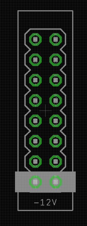
To power your Noise Engineering module, turn off your case. Plug one end of your ribbon cable into your power board so that the red stripe on the ribbon cable is aligned to the side that says -12 V and each pin on the power header is plugged into the connector on the ribbon. Make sure no pins are overhanging the connector! If they are, unplug it and realign.
Line up the red stripe on the ribbon cable so that it matches the white stripe and/or -12 V indication on the board and plug in the connector.
Screw your module into your case before powering on the module. You risk bumping the module's PCB against something metallic and damaging it if it's not properly secured when powered on.
You should be good to go if you followed these instructions. Now go make some noise!
Noise Engineering modules are reverse protected. If you accidentally installed it with the red stripe up, simply remove the power and place it correctly.
A final note. Some modules have other headers -- they may have a different number of pins or may say "not power". In general, unless a manual tells you otherwise, do not connect those to power.
Interface#

- Faders 1-4
- The main controls of Lapsus Os. The LEDs in the faders show the CV that is being passed through. When in attenuverter mode, the LED will be off at
0, allowing each fader to easily be set near0. - Uni/Bi Switches 1-4
- In the Unipolar position (left), the corresponding channel attenuates the input signal. In the Bipolar position (right), the upper half of the corresponding channel fader attenuates the input signal, the lower half of the fader inverts and attenuates the signal.
- Offset inputs 1-4 (
+) - Sending a signal to these inputs adds an offset to the input, controlled by the fader and the mode switch.
- Attenuating/attenuverting inputs 1-4 (
x) - Sending a signal to these inputs attenuates/attenuverts the signal, depending on the position of the channel fader and switch.
- Outputs
- Each channel has a pair of identical outputs. If nothing is sent to either input of a channel, an offset will be generated and output here, useful for controlling parameters on other modules with a single fader.
Rear-board switches#
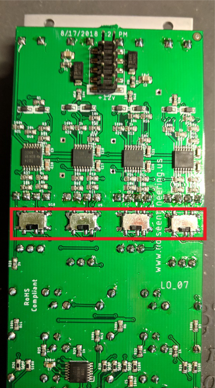
Four switches on the back of the module (show below in red) invert the corresponding channel, allowing for creative mounting in either direction. Note that each channel must be switched independently to fully reverse the functionality.
Patch tutorial#
- Patch 1
- Set a channel switch to the left position and patch the outputs to CV inputs on another module (for instance, Loquelic Iteritas). The fader becomes an easy-to-use controller for those parameters. Patch the rest of the Lapsus Os channels to other parameters in your system to create an expressive and intuitive interface.
- Patch 2
- Patch a CV signal (such as an LFO) into the attenuverting input of a channel. Set the channel switch to the right position, and patch the output to a bipolar CV input in your system. Tweak the fader to attenuvert and dial in the perfect amount of modulation on the fly.
- Patch 3
- In a case with four voices route each Lapsus Os channel to the decay control for each voice. Use for centralized control over voicing.
Design notes#
This module was simple a module stephen wanted for his case for playing live. He wanted a simple centralized control panel that could map neighboring sliders to the knobs throughout the case so that they could be played simultaneously. The original Lapsus Os was remarkably simple, but a few versions in, we decided that rather than four outputs per channel (16 outputs? Does anyone really need 16?), we could add inputs that would give all sorts of crazy control. We agreed it should be reversible early on but it wasn't until we got it in the hands of Markus Cancilla who immediately pointed out that Uni/Bi switches should be mid-panel. On that version, they were at the top, and completely in the way. It was so obvious! Markus was hired shortly after giving us that feedback...
Warranty#
We will repair or replace (at our discretion) any product that we manufactured for one year after initial purchase as long as we are able to get the parts to do so. This warranty does not apply to normal wear and tear, including art/panel wear, or any products that have been modified, abused, or misused. Our warranty is limited to manufacturing defects.
Warranty repairs/replacements are free. Repairs due to normal wear, user modification, or other damage are charged at an affordable rate. Customers are responsible for the cost of shipping to Noise Engineering technicians for repair.
All returns must be coordinated through Noise Engineering; returns without a Return Authorization will be refused and returned to sender.
For immediate issues with new modules, please contact your dealer for a replacement. Otherwise, please contact us if you think one of your modules needs a repair.