Ataraxic Translatron Manual#
Classic arcade sounds in the Eurorack format.
Overview#
Ataraxic Translatron is a linear feedback shift register oscillator similar to those used in the first generation of home video game consoles and many classic arcade games.
Linear feedback shift registers are an ingenious way to produce a variety of sounds with an extremely small amount of hardware. The Atari VCS used only around 35 logic gates to produce all of its sounds. The complexity of tone for relatively minimal hardware made this synthesis technique common for sound where hardware costs were the primary development constraint. As video games entered popular culture these sounds became iconic but have seldom made it out of the video game world except when sampled from the games themselves or as their own genre of music “chiptunes”. The Ataraxic Translatron gives you classic arcade sounds in Eurorack format to be used just like any other VCO.
13 patches vary from a simple square wave to white noise with your favorite arcade sounds in between. All tones are available in 6 octaves range. A standard 1 volt per octave pitch control and CV control of the current patch are squeezed into a compact 4HP. An external clock mode that allows an external clock to drive the shift register allows for additional tone generation, modulation and gate generation.
- Type: LFSR VCO
- Size: 4 HP
- Depth: .8 inches
- Power: 2x5 Eurorack
- +12 V:
<50 mA - -12 V:
<59 mA - 5 V:
0 mA
Power#
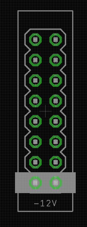
To power your Noise Engineering module, turn off your case. Plug one end of your ribbon cable into your power board so that the red stripe on the ribbon cable is aligned to the side that says -12 V and each pin on the power header is plugged into the connector on the ribbon. Make sure no pins are overhanging the connector! If they are, unplug it and realign.
Line up the red stripe on the ribbon cable so that it matches the white stripe and/or -12 V indication on the board and plug in the connector.
Screw your module into your case before powering on the module. You risk bumping the module's PCB against something metallic and damaging it if it's not properly secured when powered on.
You should be good to go if you followed these instructions. Now go make some noise!
Noise Engineering modules are reverse protected. If you accidentally installed it with the red stripe up, simply remove the power and place it correctly.
A final note. Some modules have other headers -- they may have a different number of pins or may say "not power". In general, unless a manual tells you otherwise, do not connect those to power.
Interface#
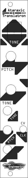
- Pitch Knob
- The pitch knob allows for adjusting the pitch through two octaves range when not in clock mode.
- Tone Knob
- The tone knob selects which feedback network is used and therefore what tones the module produces. The AT has 13 patches that increase in harmonic complexity as the patch increases. When used with an external tone CV the tone knob scales the tone CV. The current patch is displayed on the seven segment display
- Tone CV
- The tone CV allows for voltage control over the current tone. It has an approximate range of 0-6 Volts across the entire patch range. Any over/under voltage is safely clamped.
- Pitch CV
- The pitch CV provides a standard 1 volt per octave control over the output pitch. The valid input voltage range is 0-8 Volts. Any over/under voltage will be safely clamped to the maximum/minimum values.
- The module produces six octaves of perceptibly continuous pitch. Due to quantization errors at high speeds some patches will have a slight pitch quantization at higher frequencies. This is itself an interesting effect.
- The pitch CV input is also used as the clock input when used with an external clock. See the clock source switch section for a description of this usage.
- Clock Source Switch
- The clock source switch selects if the module is using the internal timebase from pitch CV or an external clock. When the switch is in the CV position the pitch input works as 1 Volt per Octave. When in clock mode the pitch CV input becomes a binary clock that drives the shift register oscillator on rising edges. The input is a Schmitt trigger with a low threshold of around 2 Volts. Input in this mode is over and under voltage protected so it can be safely driven with any standard eurorack signal. The maximum frequency which the LFSR can be driven is around 160 kHz.
- Output
- The output is DC coupled digital waveform that varies from approximately 0 to 6.5 volts. Try using it as a randomized clock source too!
Tone Generation#
The core of the Ataraxic Translatron is a 16 bit linear feedback shift register with adjustable taps which are XORed together to produce the output tone. Most patches correspond to maximal length sequences. The details of the taps are in the table below.
The input pitch CV is converted from 1v/8va to a period for the desired pitch which is then scaled by the current patch’s cycle length. This is used to set a timer that controls when the LFSR update happens. When in clock mode this update happens on any rising clock.
All patches are maximal length except E which has the interesting property that the tone that is produced is based on what the shift register state is at the time it is selected.
| Tone | Taps | Length |
|---|---|---|
| 0 | 0,1 | 3 |
| 1 | 1,2 | 7 |
| 2 | 2,3 | 15 |
| 3 | 2,4 | 31 |
| 4 | 4,5 | 63 |
| 5 | 5,6 | 127 |
| 6 | 3,6 | ? |
| 7 | 3,4,5,7 | 255 |
| 8 | 4,8 | 511 |
| 9 | 6,9 | 1023 |
| A | 8,10 | 2047 |
| C | 3,9,10,11 | 4097 |
| E | 2,10,12,13 | ? |
Calibration of Tuning#
The pitch CV response of the Ataraxic Translatron is controlled by an linear resistor divider network. To calibrate the tuning attach a volt meter (preferably 4+ digit) to the test points TPCV and TPGND on the rear panel and adjust the trim pot.
The voltage measured should be 0.075 times the input voltage applied to the CV input. A reasonable way to tune the scale is to use an adjustable voltage source to generate 3.00 volts then adjust the AT tuning trim until the test points read 225 mV.
It is also easy to use a stroboscope and a calibrated voltage reference to adjust the linearity control by tuning using an octave interval.
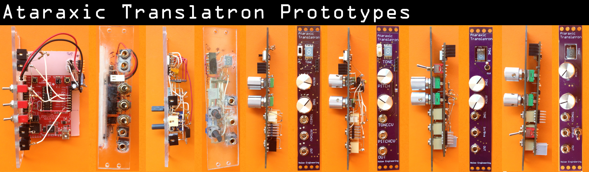
Genesis and Design Notes#
The first prototype Ataraxic Translatron was built on a lark using a TI MSP430 launchpad and a bit of scrap plastic super-glued together. It was a dual shift register (5+4 bits) similar to the LFSR in the TIA. It was external clock only as the chip on the launchpad does not have a decent ADC for pitch. I plugged this into a friend’s rig and it was an instant hit.
A further prototype was built with a better CPU for the task (MSP430F2013) along with an LED display for user feedback. A few hard lessons in linearity and signal conditioning were learned and some fun software puzzles completed (computing an exponent without multiply for example) Around 10 prototypes later the product was ready to manufacture.
This constraints of this module can be summarized very simply “LFSR VCO in 4HP”. This immediately dictated a far less than general tap structure for the LFSR due to the lack of space for a user interface. Check out the Harvestman’s Zorlon Cannon if you want a fully flexible LFSR! 4HP also ruled out separate coarse and fine pitch knobs so the design ended up with a two octave range compromise. Another important decision was to use a single 16 bit LFSR rather than multiple registers. This was primary an aesthetic decision to keep the module simple and to the point. These additional tones can be generated using an AT to drive a second AT in clock mode.
The choice of CPU was perhaps the most important decision. The F2013 seemed like a good choice due to its built in 16-bit relatively fast ADC. It ended up just barely up to the task. Ataraxic Translatron has less than 4 bytes of flash free and there are minor tuning artifacts above 6 octaves due to the precision of the internal timer. Having a 16-bit ADC on the same substrate as a CPU is also a very noisy proposition which took a lot of time to get workable.
All of the software was written in assembler using TI’s Code Composer Studio and Sublime 2.
Warranty#
We will repair or replace (at our discretion) any product that we manufactured for one year after initial purchase as long as we are able to get the parts to do so. This warranty does not apply to normal wear and tear, including art/panel wear, or any products that have been modified, abused, or misused. Our warranty is limited to manufacturing defects.
Warranty repairs/replacements are free. Repairs due to normal wear, user modification, or other damage are charged at an affordable rate. Customers are responsible for the cost of shipping to Noise Engineering technicians for repair.
All returns must be coordinated through Noise Engineering; returns without a Return Authorization will be refused and returned to sender.
For immediate issues with new modules, please contact your dealer for a replacement. Otherwise, please contact us if you think one of your modules needs a repair.
Special thanks#
- Eric Cheslak
- Shawn Jimmerson
- Shawn Cleary
- Anthony Baldino
- Matt Lange